MacFi-V4 · Public address, mass communication and emergency communication system
Public Address | Mass Communication | Emergency Communication System The need for multiple devices to handle your critical messaging can be eliminated using the MacFi-V4
The MacFi-V4 offers a great deal of functionality in a compact and inexpensive package. The system's two audio zones provides your corporate messaging to both customers and staff, and since it is connected to activation switches and sensors, it is always ready to deliver critical audio announcements in the event of an emergency.
The MacFi-V4 delivers the verbal instructions calmly, and safely to guide everyone out of harm's way using Mackenzie's Contact Maintenance and Control (CMAC) software over the Internet. Emergency messages are activated, personnel can be notified via SMS/Text, Email, or Voice Calls.
Overview
Key features
- 500 messages and over 100 hours of audio capacity
- Local start inputs for critical announcements, activated by contact closure, open collector or logic
- Playing relay for control of downstream gear
- Message 1–6 active relays on the MacFi-V4E
- Line level audio inputs, adjustable
- Line and speaker level outputs, adjustable
- Local record capability
- USB port and SD card for local file transfers
- RS-232 serial port for configuration and control
- Wall or shelf mount, optional rack mount
- Wide power supply range (9–32 VDC)
- Standard 1 year warranty
- CMAC on the MacFi-V4E: two zones of scheduled messaging
- CMAC: text to speech message entry
- CMAC: notification via SMS, e-mail or voice call
- CMAC: critical announcement activation reports
- CMAC: remote updating of audio files
- CMAC: system clock management and syncing
- CMAC: diagnostics and firmware updates
- CMAC: instant control of system settings
- CMAC: audio level control and balancing
- CMAC: enhanced background music support
Applications
- Public address
- Mass notification
- Emergency communication
- Scheduled public service announcements
- Marketing messages
- Background music
Specifications
| Audio | |
|---|---|
| Zones | 2 audio zones |
| Audio inputs | 2 line inputs, 600 Ω transformer isolated, rear panel adjustable; internal electret microphone |
| Audio coding | Recording MP3 (128 kbps); playback MP3 (32–320 kbps, VBR) or 16 bit WAV, 44.1 kHz |
| Bandwidth | 50 Hz to 15 kHz |
| Signal to noise | 85 dB typical; dynamic range 85 dB typical |
| Distortion (THD) | < 0.5% at 1 kHz, typical |
| Outputs | 2 line outputs, 600 Ω transformer isolated; 2 speaker outputs, 4 Ω / 8 Ω, 10 W rms max. each |
| Messages and storage | |
| Capacity | 500 messages, over 100 hours of audio |
| Recording | Local recording |
| Transfer | USB port and SD card |
| Memory | SD card, 8 GB typical (up to 32 GB); 599 message positions |
| Control | |
| Start inputs | 6 message start inputs and 1 stop; up to 500 with ICM-50 modules (50 inputs each, up to 10) |
| Relays | Playing relay for downstream gear; message 1–6 active relays on the MacFi-V4E |
| Serial | RS232 for configuration and control |
| Network | CMAC software over the Internet; staff notified by SMS, email or voice call |
| Modes | Standard, play once per closure, play while active, re-trigger; plays and pause by DIP switch or RS-232 |
| Interfaces | Ethernet 10/100BaseT, RJ45 (MacFi-V4E) |
| Clock | Real time clock, ±30 seconds per month typical; updated through CMAC |
| Physical | |
| Mounting | Wall or shelf; optional 1U rack adapter; 18 gauge cold rolled steel, black powder coat; made in the USA |
| Power | 9–32 VDC (12/24 VDC nominal), 3 A max. with amplifier, 250 mA without |
| Warranty | 1 year standard |
| Dimensions | 10″ W × 5.5″ D × 1.5″ H |
User manual in brief
Installation
The MacFi-V4 is an MP3 digital audio record / play system for audio notification, with two audio channels, over 500 messages and hundreds of hours of MP3 audio on a user accessible SD card. Its 3-way wall mount chassis (cold rolled steel, black finish, 10″ W × 6.5″ D × 1.6″ H) mounts on a wall or a shelf, or in a rack with the optional 1U adapter (MacFi-V4 RM-KIT). With no moving parts it suits automatic unattended operation, also in harsh environmental or mobile conditions. The MacFi-V4E adds time based playback, a background music feed, Internet based control and six message relays.
- Find a space on the wall or table; for table top use, fit the included rubber feet. Leave 6″ in front of both sides of the unit for access to the controls and wiring.
- Mount the unit with its wiring at least 18″ away from the power supply or other equipment that generates electrical noise.
- Connect the audio inputs and outputs, then the control inputs and outputs.
- Set the DIP switches to the desired operation.
- With the optional power supply, make sure a standard, non-switched electrical outlet is available.
- Optionally connect earth ground to the 8-32 stud provided.
- Connect and apply power, then test the unit’s operation.
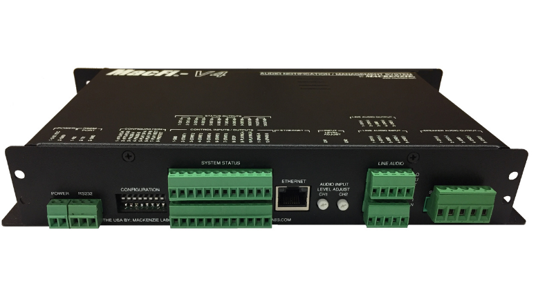
Power, audio and network connections
- Power (2 pos, 3.81 mm pluggable Euro connector): pin 1 12/24 VDC at up to 3 A, pin 2 ground. The input range is 9–32 VDC; current depends on the speaker output power required (3 A maximum with the power amplifier, 250 mA without). The unit is internally fused at 3 A. The quikey gives 12 VDC at 1 A or 24 VDC at 0.5 A for 4 W through the speakers; use a higher capacity supply for more speaker power. Optional power pack MacFi-V4-PS (12 VDC, 1 A).
- Line audio input (lower 5 pos, 3.81 mm Euro): pin 1 channel 1 (−), pin 2 channel 1 (+), pin 3 system ground for shielding, pin 4 channel 2 (−), pin 5 channel 2 (+). Two 600 Ω transformer isolated channels, for recording messages or as a feed through the system when no message is playing; rear panel potentiometers set the sensitivity for up to +15 dBV. Each input can be configured for line or microphone level.
- Line audio output (upper 5 pos, 3.81 mm Euro): same pin order as the input. Two 600 Ω transformer isolated channels drive external amplifiers or processors at up to +6 dBV; the front panel potentiometers set the level.
- Speaker output (5 pos, 5 mm Euro): pin 1 channel 1 (−), pin 2 channel 1 (+), pin 3 system ground for shielding, pin 4 channel 2 (−), pin 5 channel 2 (+). Two bridged outputs from a class D amplifier, each up to 10 W into 4 Ω or 8 Ω depending on the input power, so many installations need no external amplifier.
- Never reference either speaker output terminal to ground; this causes incorrect operation and may damage the unit. Connect the speaker directly across the output.
- Ethernet (MacFi-V4E, RJ45): connects the unit to a LAN with Internet access for remote updates and control with Mackenzie’s CMAC software; DHCP by default.
- RS232 port (3 pos, 3.81 mm Euro): pin 1 receive (input), pin 2 transmit (output), pin 3 ground; see RS-232 control below.
Control inputs and relay outputs
The lower 12 position connector (3.81 mm Euro) starts and stops messages and carries the playing relay. Inputs are activated by mechanical contact closure or an open collector driver to common (12 VDC at 5 mA). Relay outputs are dry contacts rated 24 VDC at 1 A, non-inductive load.
- Pin 1: common.
- Pins 2 to 7: Start 1 to Start 6 inputs, one per message 1 to 6.
- Pin 8: stop input.
- Pins 9 and 10: play relay, common and normally open. The relay is held for the whole play sequence (the message, its repeats and the pauses) and drops for about 100 ms between queued sequences.
- Pins 11 and 12: spare relay 1, common and normally open.
- Status outputs (MacFi-V4E, upper 12 position connector): pins 1 to 12 are the common and normally open contacts of six relays, message #1 to #6 playing, to signal downstream gear such as lighting or strobes. Only the relay of the message playing is active; none is active for messages above 6.
- More than six start inputs come from ICM-50 input control modules, each adding 50 message start inputs, for up to 500.
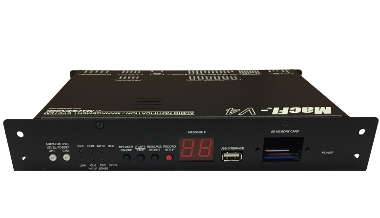
Front panel controls
- Speaker on/off: toggles the internal monitor speaker between channel 1, channel 2 and off. It switches on automatically when a message is played from the front panel and off when messages play from contact closure or RS-232.
- Start/Stop: starts or stops the current record or play operation. Pressing it twice within 1 second during recording aborts and deletes the recording. Pressing and holding it while idle enters baud rate select mode.
- Message Select: steps through the message positions on the Message # display (in play mode only stored messages are shown); press and hold to jump ten positions.
- Record Setup (red): enters or leaves record setup mode (the record LED blinks); it has no effect during a recording. Press and hold while idle to choose the recording input, shown as L1 (line input 1), L2 (line input 2) or cc (internal microphone); Message Select changes it, and after 2 seconds the choice is stored in non-volatile memory. Held while powering up, it formats the SD card.
- Audio input level (two, rear panel) and audio output level (two, front panel, setting line and speaker outputs together): clockwise raises, counter-clockwise lowers the level of each channel.
Indicators and display
- SPKR (yellow): off when the monitor speaker is disabled; one blink for channel 1, two blinks for channel 2.
- CH1, CH2 audio sense (yellow): off with no audio, blinking on audio peaks, on with a high level; adjust the input level until the LED lights when recording. Inactive when the microphone is selected.
- REC (red): blinking in record setup mode, on while recording.
- LINK (yellow, V4E): the Ethernet connection is ready. SYS (yellow, V4E): the Ethernet is being configured. CON (green, V4E): connected to the Mackenzie cloud servers and available for remote download and control.
- ACTV (green): a playlist is active; blinks while a playlist message plays. POWER (green): the unit has power.
- Message # display (two seven segment digits): 01–99 solid for the message playing or recording; _1 alternating with 00–99 for messages 100–599; cycling segments when no messages are recorded; both decimals blinking in record setup when the chosen position already holds a message; right decimal solid when delay, pause, repeat or baud rate was set via RS-232.
- Display codes: CO, dL, uP for a Complete, Delta or Upload folder on the USB key; Er error; FC bad block memory test (formatting the SD card); nF no SD card; xx the number of messages at boot; 115, 57, 96, 12 the baud rate; two blinking dashes when recording is attempted in memory protect mode.
Configuration switches
An 8 position DIP switch tailors the operation; a switch up is OFF, down is ON. The switches are read only at power up; to change them, disconnect power, set the switches and re-apply power.
- Switches 1 and 2, number of plays (global, for messages started from the remote activation connector; RS-232 activations are not affected): OFF OFF once, OFF ON twice, ON OFF three times, ON ON four times (or a custom count set with the RS-232 PLS command).
- Switches 3 and 4, pause between plays: OFF OFF 1 second, OFF ON 5 seconds, ON OFF 10 seconds, ON ON 30 seconds (or a custom pause set with the PAS command).
- Switches 5 and 6, play method: OFF OFF standard operation, OFF ON play one sequence per closure, ON OFF play while active, ON ON re-trigger.
- Switch 7, play next: ON lets the Start 6 input (pin 7) play the next message sequence; the first activation after power on plays the first message in memory. All modes are supported and Start 1–5 are disabled.
- Switch 8, memory protect: ON locks the message memory against local analog recording and USB download; CMAC updates still work.
Play modes
A message sequence is the message played the selected number of times with the selected pause between plays, as set by the DIP switches or RS-232 commands.
- Standard operation: a momentary closure plays one sequence of that input’s message. A maintained closure repeats the sequence until the input is released, then the current sequence finishes. With several inputs held, the unit plays one sequence of the first message and cycles through the other active ones in order of activation; the lower input number wins when inputs arrive at exactly the same time.
- Play one sequence per closure: a maintained input plays the sequence once; the input must be inactive for 100 ms before it is recognized again, while other inputs are served normally. A message may be queued more than once; activations beyond a full queue are ignored. A stop ends the current message and the next queued one starts.
- Play while active: the message plays as long as the control signal is held and stops at once when it is removed; if the input is still held after the sequence, another sequence starts. With several inputs held, only the highest priority message plays and repeats. No queuing.
- Re-trigger: a new activation, of another message or the same one, stops the playing message and plays the new one. A maintained activation plays the sequence once. No queuing.
- Playlist messages (MacFi-V4E) stop and give way to any message triggered by contact closure or serial command.
Loading and erasing messages
Audio files are WAV (44.1 kHz, 16 bit) or MP3 (44.1 kHz, 32–320 kbps, VBR); local recordings are made as MP3 at 128 kbps. Messages may be mono or stereo, but only the left channel plays, and may last from a couple of seconds to several hours. Files are named by message number (1.mp3 or 1.wav for position 1, up to 599); numbers above 599 are ignored, and when an MP3 and a WAV share a name the MP3 plays.
- Local analog recording: connect the source to an audio input and the audio output; press Record Setup (the record LED blinks, the display shows 01, and blinking decimals mean the position is in use); choose the position with Select; play the source and adjust the input level until the audio sense LED is solid; rewind the source, press Start/Stop and start the source (the record LED is solid); press Start/Stop to end. Record setup times out after 1 minute of inactivity.
- SD card: remove the cover plate and press the card to eject it. On a Windows computer, copy all audio and configuration files into the card’s “DAVE” folder (create it if missing) and delete files no longer needed. Insert the card until it clicks; the unit resets, reloads the files and initializes. The card can be swapped with power on; up to 32 GB.
- USB memory key (type A, up to 32 GB), the quickest method: a “Complete” folder formats the SD card and loads the folder’s audio and configuration files; a “Delta” folder replaces files of the same name and adds new ones; an empty “Upload” folder receives a copy of all audio files from the unit. More than one of these folders on a key is an error and nothing is transferred. Afterwards the unit resets and reloads. A firmware file placed in the key’s root folder updates the firmware.
- Complete memory erase: remove power, hold Record Setup while restoring power until the record LED stays on, then release; the display reads FC during the memory check, which can take several minutes. When the record LED goes off, the unit has no messages.
- Erasing one message: record a short message (under 1 second) into its position.
Playback activation
- Front panel: press Select until the message number shows, press Start/Stop to play, adjust the output level, and press Start/Stop to stop. Repeats and delays are not used in this mode; playback setup times out after 15 seconds.
- Contact closure or open collector: a momentary or maintained closure between a start input and ground plays that message with the selected repeat and delay settings, and the display shows its number; a closure on the Stop input stops playback. Inputs for empty or corrupt positions are ignored. The base unit reaches the first six messages, ICM-50 modules up to 500.
- Serial port: RS-232 commands can play all 599 messages.
Internet connection (MacFi-V4E)
With the Ethernet connection, Mackenzie’s Contact Maintenance and Control (CMAC) software or a provider manages the unit over the Internet. Through CMAC, emergency messages can notify staff by SMS, e-mail or voice call.
- Connect the Ethernet port with the supplied RJ45 cable to a hub or switch on the premises LAN with Internet access. The green CON LED blinks until the server connection is made, then lights solid.
- DHCP is enabled by default; on a DHCP network the unit connects to the provider’s server by itself.
- For a static IP or advanced settings (proxy server, gateway), a technician creates a configuration file with the Mackenzie NSU software and loads it through the USB port on a memory key.
- Remote loading: with the CON LED lit, the provider can download new material; the unit then resets and the messages are available for playback.
- Playlists: sequences of messages that play automatically by time of day or schedule, through channel 1 or channel 2.
RS-232 control
The RS-232 port controls playback and configuration with ASCII commands from a computer or an external controller. The protocol is 8 data bits, 1 stop bit, no parity, no flow control, at 1200, 9600 (default), 57,600 or 115,200 baud. Commands are typed at the MFI> prompt and end with a carriage return
- Baud rate: press and hold Start/Stop for one second while idle; the display shows the current speed (12, 96, 57 or 115). Wait 5 seconds to keep it, or press Message Select to step through the speeds and wait 5 seconds to save the one shown in non-volatile memory.
- HyperTerminal: create a connection on the serial port the unit is connected to (for example COM 1), set the bits per second to the unit’s rate, 8 data bits, no parity, 1 stop bit and no flow control, then press Enter to get the MFI> prompt.
RS-232 commands
Commands marked with an asterisk ask for Y/N confirmation.
- PLY
, : play a message (1–599), repeat times, with a pause in seconds between repeats; PLY6,10,5 plays message six ten times with five seconds between. Without a number it plays the next message in memory (message 1 after power up); without repeat it plays once; without pause it waits one second. PLY commands sent during playback are queued in order. - STP: stop playback or recording and clear the whole queue.
- REC
, - INP<1-3>: recording input, 1 channel 1 line input, 2 channel 2 line input, 3 internal microphone.
- DLY
: delay in seconds before the first play; PAS : pause in seconds between repeats (overrides switches 3 and 4 both ON); PLS : number of plays per trigger (overrides switches 1 and 2 both ON). These apply only to contact closure triggers. - DIR: list the 600 message locations, a number for a valid message, “xx” for an empty one. DEL
- BBT*: bad block test, formats the SD card and erases all messages. CFG*: restore DLY, INP, PAS and PLS to defaults and the baud rate to 9600. SHP*: format the card and reset all settings to factory defaults (up to 10 seconds).
- RST: warm reset. SYS: firmware version and the list of messages on the SD card. LST: list the commands with their fields and values.
Troubleshooting
- No LEDs active → check that the POWER LED is on; if not, verify with a voltmeter that power is present and correctly polarized at the power connector.
- A message will not play → press Select to check that messages are loaded and that the message number exists; try a message that is loaded. When activating from the control inputs, measure with a voltmeter that the activating device grounds the start input.
- No sound from the audio output → nothing is playing if the Message # display is blank; check the Euro connector wiring and screws; turn the output level clockwise; try the speaker output instead of the line output; messages may not play while CMAC is downloading to the unit.
- No sound from the monitor speaker → press the Speaker button and check that the SPKR LED is on or blinking.
- CON LED does not light after power on → check the Ethernet cable at the unit and at a hub or switch with Internet access; one LED on the Ethernet jack should be lit and the other blinking, otherwise try another cable or port; check Internet access from a computer on the same LAN; if network settings changed, tell the provider, as a new configuration file may be needed.
Documents
| Document | Content | Format |
|---|---|---|
| Spec sheet | Specifications | |
| Operation guide | User manual, version 1.5 |
Images