MB-701 · In-vehicle automatic announcement system
A single integrated device that can manage up to four different subsystems. Multiple channels of audio playback, signage control, PA microphone interface, automatic level control, and the amplifier...Anything else you need?
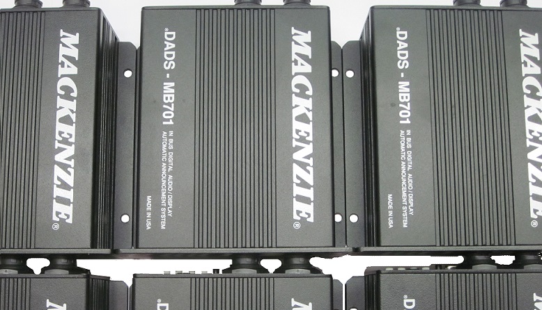
The DADS-MB701 is our third generation in vehicle playback system. It is a fully featured automated next stop destination announcement and signage control device. It incorporates two audio outputs with associated text for the internal channel, industry standard J1708/J1587 triggering, automatic level control and highly reliable operation in a ruggedized package!
Overview
Key features
- High reliability / ADA transit rated
- Two channel, high quality audio
- Integrated 20 W amplifier per channel
- Automatic level control
- High speed USB downloadable
- Integrated memory database storage
- Variable message sign support
- J1708 / J1587 triggering
- RS232 auxiliary communications port
- Backwards compatible with DADS-A1214 systems
- Operator microphone interface for ad hoc announcements
- Optional: wireless Ethernet (802.11b/g) for file updates
- Optional: real-time clock with battery backup
- Optional: audio level adjustment by time of day
Specifications
| Audio | |
|---|---|
| Channels | 2 high-quality audio channels; text associated with the internal channel |
| Amplifier | Integrated 20 W per channel |
| Level | Automatic level control |
| Audio coding | MPEG-1 Layer 3 (MP3) |
| Signal to noise | 85 dB |
| Distortion (THD) | < 0.1% |
| Audio inputs | Operator PA microphone with push to talk; 2 ALC microphones; background music line input |
| Messages and storage | |
| Storage | Integrated memory database |
| Transfer | USB memory key |
| Signage | Variable message sign support |
| Memory | FLASH, SD card |
| Control | |
| Triggering | J1708 / J1587 |
| Serial | RS232 auxiliary port, 115.2 kbaud, 8 N 1 |
| Compatibility | Backward compatible with DADS-A1214 systems |
| Relays | Form C playing relay per channel, 1 A at 24 VDC |
| Start inputs | Stop request and lift request; microphone zone select, volume up/down; system disable |
| Physical | |
| Rating | High reliability, ADA transit rated |
| Power | 9–32 VDC; internal self-resetting fuse |
| Interface | DB-50M main interface; 8-pin and 4-pin sealed circular connectors; USB type A |
| Mounting | Painted aluminum extrusion; flanges with mounting holes |
| Environmental | Storage −40 to +70 °C; vibration 4 G RMS, 5–150 Hz operating, 8 G RMS, 100–1,100 Hz endurance; shock 30 G, 6 ms; FCC Part 15, Class A |
User manual in brief
Installation
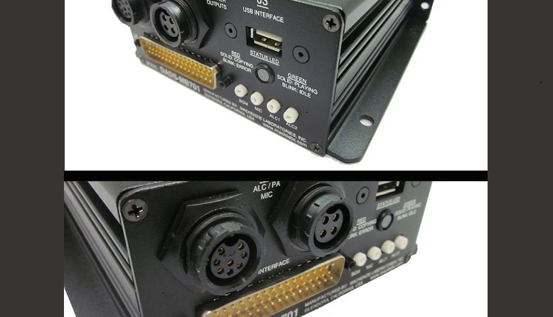
The DADS-MB701 is a fully featured automated next stop and destination announcement device for buses. It has four interface connectors and mounts by its flanges with mounting holes. Channel 1 drives the internal zone speaker network and channel 2 the external zone.
- Power: 24 VDC nominal, range 9–32 VDC (12 or 24 VDC vehicle systems); internal self-resetting fuse. Power and ground can run as three individual 20 gauge wires each, or as one 16 gauge wire to the power source spliced into three 20 gauge wires at the DB50 connector. Connect chassis ground close to the unit.
- Typical wiring: 16 gauge for speaker networks, 20 gauge for control and microphone switch lines, shielded pairs (West Penn 77291) for the microphones, Belden 9841 or 5340FT (plenum 89841 or 6340FT) for J1708 and Belden 8761 (plenum 88761) for RS232. Gauges and types are for reference; select them for each wiring run.
Main interface, J4
DB-50M (Amp 205212-1); mating connector a standard DB50 female, Amp 205211-1. Groups of three pins are connected together internally.
- Pins 1, 18, 35: chassis ground. Pins 2, 19, 36: power return. Pins 3, 20, 37: system power.
- Pins 7, 24, 41: CH1 balanced line level output (non-inverting, ground, inverting). Pins 6, 23, 40: CH2 balanced line level output. For auxiliary use.
- Pins 8, 25, 42: J1708 port (non-inverting, inverting, shield).
- Pins 10, 27, 44: RS232 port (transmit, receive, return), to DB9 pins 2, 3 and 5; 115.2 kbaud, 8 N 1, no flow control.
- Pins 12, 29, 46: CH1 playing relay; pins 11, 28, 45: CH2 playing relay (normally closed, normally open, common). Form C dry contacts, 1 A at 24 VDC, non-inductive load.
- Pin 14: message 1 play input (stop request). Pin 31: message 2 play input (lift request).
- Pin 32: microphone volume up. Pin 15: microphone volume down. Pin 16: internal zone enable. Pin 49: external zone enable. Pin 33: system disable.
- Pins 9, 26, 43 and 50: input commons (0 V, system ground). Pins 13, 30, 47, 48: spare inputs.
- Pin 17: background music input, single ended line level; pin 34: audio ground for BGM.
ALC, PA microphone, speakers and USB
- J1, ALC / PA interface: 8 pin sealed circular, Conxall 4282-8SG-300; mating Conxall 3282-8PG-3DC. Pins 1 (+) and 2 (−): CH1 (internal zone) ALC microphone; pins 3 (+) and 4 (−): CH2 (external zone) ALC microphone; pin 5: operator microphone push to talk; pins 7 (+) and 6 (−): microphone element; pin 8: input common.
- J2, speaker outputs: 4 pin sealed circular, Conxall 4382-4SG-300; mating Conxall 3382-4PG-3DC. Pins 1 (+) and 2 (−): CH1 speaker output; pins 3 (+) and 4 (−): CH2 speaker output. Each speaker network 4 Ω or more.
- J3: USB type A, female, for standard USB memory keys.
- Front panel potentiometers, set with a small Phillips screwdriver (they have no backing; do not force the tool): BGM level, operator microphone level, CH1 ALC threshold and CH2 ALC threshold. Clockwise raises the level or the ALC sensitivity.
Automatic level control
The system constantly averages the noise picked up by the ALC microphones in the vehicle and, when a message starts, raises the output level to overcome it, by up to 19 dB. The level does not change during a message, so microphone placement relative to the speakers matters little, unless the speakers also carry live pages or background music; then keep the microphones away from them.
- Place the microphones where the passengers will be, since the ALC is designed to overcome the noise of more people on board.
- Set up the system with the vehicle running and no passengers, so the base level matches the vehicle’s own noise.
Operator microphone and control inputs
Control inputs activate when connected to input common. Each is optically isolated and powered from the unit’s input power, with a 2.2 kΩ resistor in series inside the unit. The wiring diagram shows a control panel with lift request, stop request, mic volume up and mic volume down pushbuttons and external zone enable, internal zone enable and system disable toggle switches.
- Push to talk: routes the driver’s microphone to the selected zones and stops any playing pre-recorded message; messages triggered during the session are ignored.
- Zone enable: internal zone only, external zone only, or both zones when neither signal is active.
- Microphone volume: 16 steps, +11, +7, +3, 0 (default), −4, −8, −11, −15, −19, −22, −26, −30, −33, −37, −41 and −44 dB, one step per activation; saved in non-volatile memory at the end of the session, so it survives power outages.
- System disable: neither announcements nor microphone audio reach the speakers, and the signage interface is disabled.
- Stop request and lift request: play message 1 or 2 through channel 1; if a message is playing on that channel, the new one is queued. Standard status responses are sent over J1708 and RS232.
- Playing relays: each channel’s Form C relay activates while a message or the microphone plays through that channel.
- Background music: audio on the BGM input plays through the internal amplifiers to the speakers; without it, passengers hear silence between messages.
Communications and message loading
- J1708 / J1587: transit standard triggering from mobile data terminals (MDT). The wiring diagram shows the J1708 pair shared with the mobile data terminal and an LED sign (Sunrise NXTP7X962M) powered from the vehicle.
- RS232: an operator can control the system or download data from a laptop.
- Memory: audio and configuration files on the internal SD card (FAT formatted, FLASH).
- USB loading: on insertion of a USB key with valid audio files, the unit stops normal operation and copies them to the SD card; the red LED is on and J1708 and RS232 commands are not accepted. When done, the green LED blinks until the key is removed, then the unit resets.
- Files must be in specific folders, to prevent unauthorized transfers: “Complete” erases the SD card and rewrites everything; “Delta” overwrites only the files it holds. If both folders are on the key, no update is made and the red LED blinks until the key is removed.
Status LED and troubleshooting
A dual colour LED on the front shows the status by its blink cadence. Idle is a short green flash (250 ms) every 2 seconds; green steady while playing on any channel; red during a USB transfer, off 250 ms between files; alternating red and green while the firmware updates.
- Fast green/red alternation for 1 second, then reset → no application code and no SD card installed.
- Red double flash, then reset → no application code.
- Red flash (250 ms) every 2 seconds → no sentence.cfg file on the SD card.
- Two red flashes, then a 2 second pause → no SD card installed.
- Three red flashes, then a 2 second pause, until the key is removed → memory full during a USB transfer, or invalid USB key.
- Red, 1 second on and 1 second off, until the fault clears → audio amplifier fault.
- Red blinking after inserting a USB key, no update → both “Complete” and “Delta” folders are on the key; keep only one.
Documents
| Document | Content | Format |
|---|---|---|
| Spec sheet | Specifications | |
| Operation guide | User manual, version 1.1 | |
| Quikey: connectivity detail | Connectivity detail |
Images
Related models: Transit
| MB-701 | In-vehicle automatic announcement system | This page |
|---|---|---|
| DADS In Vehicle | Communication system operator interface | |
| DADS Platform | Audio/visual public access system |